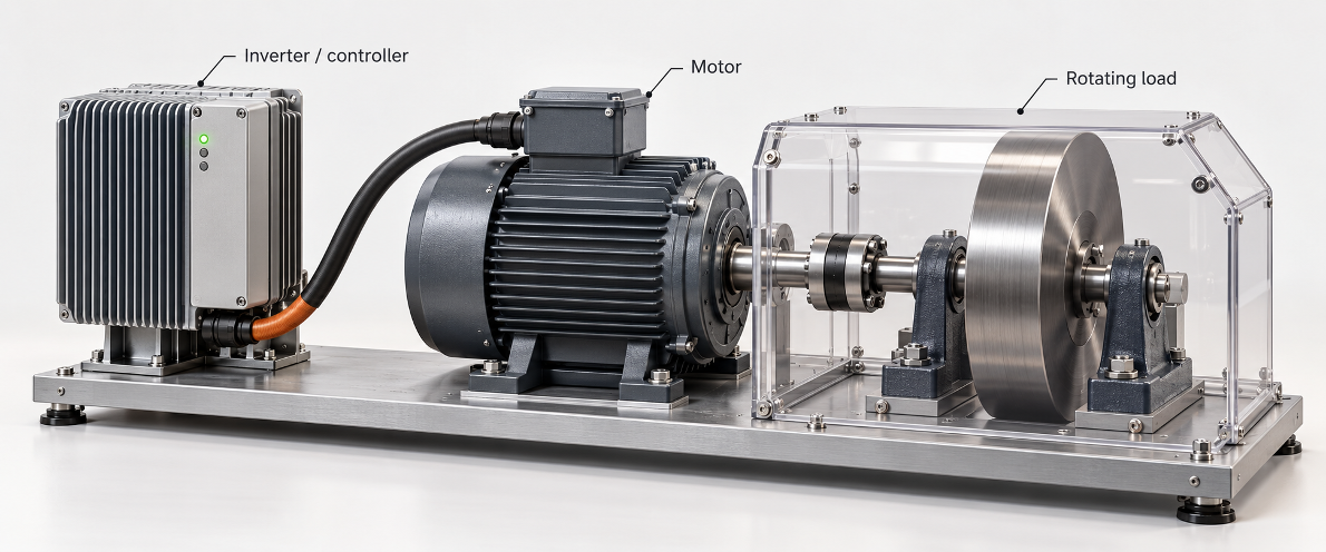
Physical system overview. The inverter controls electrical power delivered to the motor. The shaft and coupling turn the flywheel, which represents a rotating load. As the flywheel speeds up, it stores kinetic energy. Conceptual illustration; component dimensions and ratings are illustrative.
A motor’s rated current is only the starting point when sizing a motor controller. What happens when your load has to accelerate in 0.5s or send energy surging back during a fast stop? You may only need a moderate amount of current to keep a load spinning, but accelerating or braking demands far more from your hardware. Before selecting a controller, map out what the machine actually does, calculate peak current and DC-link supply limits, and ensure returned braking energy has somewhere to go.
The secret to avoiding costly hardware failures is starting with a complete load profile: a precise schedule of required speed, torque, acceleration, braking, and timing requirements the controller must support. For example, if a machine accelerates for 0.5 seconds, runs for 1.5 seconds, brakes for 0.5 seconds, and rests for 1.5 seconds every cycle, the controller has significantly less time to dissipate heat than if that move occurred once a minute.
Key takeaways
-
Record how long the motor needs peak current and how often that demand repeats. Use both times when checking the controller’s current and temperature limits.
-
Label the two points used for every voltage specification. State whether its value is a waveform peak or an RMS value.
-
Choose a component or circuit that can receive the braking energy. Setting a bus-voltage limit does not give that energy somewhere to go.
To size the motor controller from its requirements, we’ll first calculate the torque needed to accelerate the load and the motor current needed to produce it. Next, we’ll relate shaft speed to controller timing and determine the DC supply voltage. Finally, we’ll calculate the energy returned during braking and check where it can go. The closing checklist follows the same sequence.
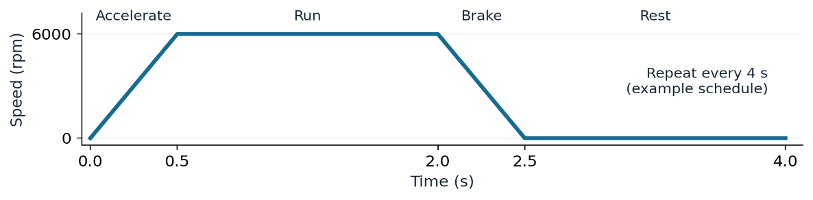
Figure 1. An example load profile: the acceleration, running, braking, and rest intervals all affect controller sizing.
1. Calculate Motor Torque and Phase Current
Assume the rotor and load together have an inertia J of 0.02 kg·m² as seen at the motor shaft. Inertia describes how strongly a rotating object resists a change in speed. For this example, accelerate the shaft from rest to 6,000 rpm in 0.5 s at a constant rate.
First convert revolutions per minute to radians per second. One revolution is 2π radians, and one minute is 60 seconds:
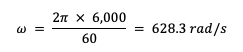
Then divide the change in speed by the acceleration time:
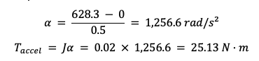
The motor must also turn the external load while accelerating it. Assume that load requires another 3.9 N·m. Add 1.0 N·m for mechanical resistance such as bearing friction, gear friction, and air drag. These are separate assumptions in this example. If a measured load torque already includes friction, adding the same friction again would count it twice.

The motor therefore needs about 30 N·m throughout the half-second acceleration. To convert that torque to current, we need a motor torque constant and its current definition.
Assume a surface-magnet synchronous motor that produces sinusoidal back EMF, the voltage generated by its rotating magnets. Assume the sinusoidal phase current is aligned with that voltage and that the controller does not use field weakening. Let the torque constant Kt be 0.25 N·m per ampere of phase-current peak.
Assume a surface-magnet synchronous motor that produces sinusoidal back EMF, the voltage generated by its rotating magnets. Assume the sinusoidal phase current is aligned with that voltage and that the controller does not use field weakening. For this example, define the torque constant Kt as 0.25 N·m per ampere of phase-current peak. This definition is specific to the example; motor manufacturers may specify torque constants using different current conventions. Verify the convention used by the motor datasheet and simulation model before applying these calculations. For example, if the same 0.25 N·m/A were specified per RMS ampere, this 30 N·m demand would require about 170 A of phase-current peak instead of 120 A.
Under the peak-current definition, divide the total electromagnetic torque by Kt:

During the 0.5 s acceleration, each sinusoidal phase-current waveform must reach a peak of about 120 A. The current drawn from the DC source follows a different path and requires its own calculation. Each inverter transistor also conducts for only part of the cycle, so its RMS current must be calculated from its actual conduction intervals. As noted above, check which current definition the manufacturer uses before applying a motor’s listed torque constant..
These calculations help establish the controller’s required ratings. Determine how much current the hardware must carry continuously and how much it must carry briefly. Determine the supply voltage required and the highest voltage the controller’s components must withstand. Then check power at the same torque and speed.
At the end of this acceleration, the converted mechanical power is Tω ≈ 30 × 628.3 = 18.9 kW. The electrical source must also supply the power converted to heat through electrical losses. Even if the controller can deliver the required 120 A phase-current peak, the supply voltage must still be high enough to produce the requested torque at 6,000 rpm. We’ll check that in Step 3.
2. Relate Motor Shaft Speed to Current Controller Timing
For the motor controller to regulate current effectively, its control loop must update fast enough relative to the motor’s electrical frequency. The permanent-magnet synchronous motor assumes eight pole pairs: 16 alternating magnetic poles around the rotor. During one shaft revolution, the phase-current sine wave and back-EMF sine wave each repeat eight times. One full repetition is an electrical cycle. At 6,000 rpm:

The 800 Hz electrical fundamental means the phase-current and back-EMF sine waves repeat 800 times per second. Each electrical cycle therefore lasts 1.25 ms. The inverter also produces much faster PWM switching pulses within that cycle.
Assume the current controller performs 20,000 updates per second, or 20 kHz. At each update, it samples the motor current and compares the reading with the requested current. It then calculates a new PWM command to adjust the voltage applied to the motor:

The controller can adjust its command 25 times during one electrical cycle. That tells us how often it can act, but we still need to check how quickly the motor current actually responds. Processing delays can postpone the correction. Motor inductance, winding resistance, controller tuning, and available voltage also affect the response. Test or simulate a change in requested current with the intended motor. Check how quickly the measured current reaches the request and whether it overshoots or oscillates.
3. Determine Required Minimum DC Supply Voltage
The DC link is the inverter’s DC supply connection. Measure its voltage between the positive and negative supply rails. To measure motor line-to-line voltage, use two motor phase terminals instead.
A two-level inverter connects each phase terminal to one DC rail or the other. Pulse-width modulation (PWM) adjusts how long each connection lasts. Over many switching pulses, this produces the desired fundamental motor voltage.
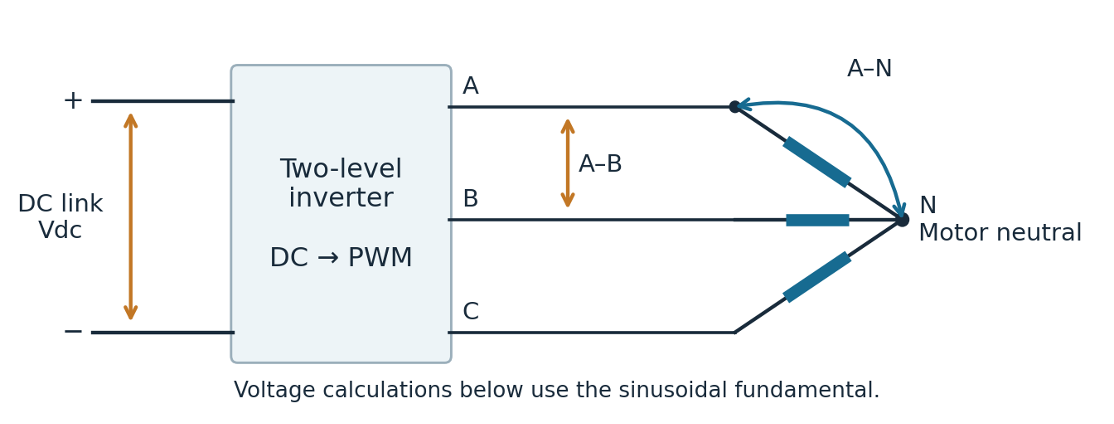
Figure 2. Block diagram of a two-level inverter. DC link, phases A, B and C and their connection to the neutral point of a motor.
Measure DC-link voltage between the supply rails. Measure phase-to-neutral voltage from terminal A to winding junction N. Measure line-to-line voltage from A to B. In this star-connected motor shown in the image above, N joins the three windings and is separate from the negative DC rail.
As the requested motor voltage increases, the inverter needs to adjust its switching pulses accordingly. Within the linear modulation range, the fundamental output voltage remains proportional to that request. Beyond this range, the inverter cannot keep increasing the sinusoidal output in the same way, and overmodulation or clipping occurs. For an ideal inverter using space-vector PWM, the largest sinusoidal phase-to-neutral peak within the linear range is:
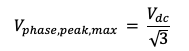
This factor comes from how space-vector PWM uses the DC supply. Infineon’s motor-control application note describes this modulation limit.
To compare voltage conventions for a different motor, suppose it needs 28 V phase-to-neutral peak. The ideal minimum DC link is:

Now suppose the motor specification says 28 V line-to-line RMS. The measurement points have changed: this voltage is between two motor terminals. Its amplitude convention has changed too: RMS replaces peak. For balanced sinusoidal fundamentals, line-to-line peak is √3 times phase-to-neutral peak. Divide a sine wave’s peak by √2 to obtain its RMS value:
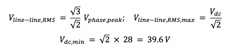
Both specifications say “28 V,” but they lead to different DC supply requirements. Check the measurement points and amplitude convention in the motor data before choosing a supply. The calculated 48.5 V and 39.6 V are ideal lower bounds. The real inverter needs additional voltage to account for winding and switch voltage drops, supply variation, and control requirements.
Return now to the motor in Step 1. Its rotating magnets generate back EMF in the windings. For the motor and current assumptions stated there, the torque constant also sets the back-EMF constant.
With sinusoidal current aligned to back EMF, converted mechanical power equals 1.5 × phase-peak back EMF × phase-peak current. Mechanical power also equals torque × shaft speed. Combine those relationships with T = KtI to find the voltage generated at 6,000 rpm:

The 181.4 V result is the DC bus voltage lower bound needed to overcome back EMF alone at 6,000 rpm. The windings also require voltage across their resistance and inductance. The transistor switches add voltage drops. Allow for the DC supply falling below nominal and for ripple on the DC link. The controller also needs enough available voltage to adjust current. Include those demands before selecting the practical supply voltage. The earlier 28 V calculations illustrated a different motor requirement.
A 48 V bus can produce an ideal phase-voltage peak of 48/√3 = 27.7 V. For this motor, back EMF reaches that value at about 1,588 rpm under the same assumptions. Winding voltage drops would reduce the available speed further. The 48 V supply therefore cannot produce the example’s 6,000 rpm and 30 N·m operating point. Field weakening changes the current command to extend speed, so it requires a separate check of motor voltage , current, and thermal limits.
Motor equation reference: MathWorks, Surface Mount PMSM. The torque constant uses total torque per phase-current peak under the amplitude-invariant dq transform (T = 1.5·P·λ_pm·i_q). Back EMF is phase peak per mechanical rad/s; MathWorks specifies K_e as line-to-line peak per krpm, which is 30.2 V/krpm for this motor.
4. Calculate Braking Energy and Plan Absorption Paths
At 6,000 rpm, energy is stored in the motion of the rotor and load. Using the same combined inertia of the rotor and load and the unrounded speed from Step 1:

During deceleration, some of the stored mechanical energy becomes heat. For this example, assume 3.0 kJ reaches the inverter’s DC link during a 0.5 s stop. Divide the returned energy by the stopping time to find the average power that the receiving circuit must handle:

During a constant-torque stop, shaft speed falls linearly to zero. Mechanical braking power also falls linearly because power equals torque × speed. Now assume the electrical power returned to the DC link has the same triangular shape over time. For this assumed shape, starting power is twice the average:

The 12 kW peak depends on that assumed shape of returned electrical power. Conversion efficiency, external load torque, and the stopping command can change the actual peak.
If a brake chopper switches the returned energy into a resistor, check the chopper’s voltage rating and pulse-current rating. Check how much energy the resistor can absorb during one stop and how hot it becomes during repeated stops. If a battery receives the energy instead, verify that it can accept charging at its actual state of charge. When it cannot, provide another receiving circuit or change the stopping schedule if the application permits it.

Figure 3. Block Diagram of Energy flowing from the Rotating load to the motor + inverter, dc link, receptive source, brake resistor and energy storage.
During regeneration, energy moves from the rotating motor and load back toward the DC link. The battery, brake resistor, or other selected storage must handle both the returned power and the energy accumulated during the stop.
Could the DC-link capacitor store all 3 kJ? Assume a higher-voltage design in which the bus may rise from 200 V to 240 V during braking. The capacitor stores more energy as its voltage rises. Use the difference between its energy at 240 V and its energy at 200 V to calculate the required capacitance.
This example’s voltage window is above the motor’s back-EMF-only requirement. Still check that 200 V can supply the motor under load, as described in Step 3. Also verify that the components can withstand the permitted bus voltage. The capacitor-energy calculation is:

The required capacitance is about 0.341 F, or 341,000 μF. Calculate the energy capacity of the selected DC-link capacitor before assuming it can absorb a full braking event. After storing the energy, the capacitor must release enough of it before the next stop. Otherwise, the next braking event starts at a higher capacitor voltage. Batteries and brake resistors also need to handle the repeated stopping schedule.
Motor Controller-Sizing Checklist
-
Record motor speed, load torque, and acceleration time. Record braking time and how often the complete motion sequence repeats.
-
Calculate motor torque and phase current. Label current as peak or RMS, and record how long each current demand lasts.
-
Check mechanical power at the required torque and speed. Include electrical power losses when calculating the power the supply must deliver.
-
At the lowest expected DC bus voltage, verify that the inverter can supply the motor voltage and control the current. Label the measurement points and peak or RMS convention for each voltage.
-
Calculate returned braking energy and the peak and average braking power. Check the ratings of the battery, resistor, capacitor, or other circuit receiving that energy.
Build the circuit in Allegro X System Capture and use PSpice to simulate the operating cases defined by the load profile. Check phase current during acceleration, confirm that the DC link provides sufficient voltage at the lowest expected supply voltage, and monitor bus-voltage rise during regenerative braking. Compare the simulated results with the current, voltage, and energy limits established in the calculations. Use motor and device models appropriate to the behavior being evaluated, and verify that the design remains within component ratings throughout the operating cycle.
Frequently Asked Questions About Motor Controller Sizing
How do you calculate if a motor is capable of driving a load?
Start with the motion you need: how fast the shaft must turn, how quickly it must reach that speed, and what resists the motion. Calculate the combined inertia of the motor rotor and attached load as seen at the motor shaft. Multiply that inertia by the required angular acceleration to find the acceleration torque. Then add the external load torque and mechanical friction, taking care to count each contribution once.
Check that the motor and controller can deliver the resulting torque throughout the required speed range. Then check how long that torque is needed and how often the move repeats. For this article’s example, the pair must deliver about 30 N·m for 0.5 s while accelerating to 6,000 rpm. A torque rating by itself does not establish that the pair can complete this move.
When does a motor controller use peak power?
A peak rating describes a short-term capability under the manufacturer’s stated conditions. The controller uses additional current when the torque command requires it and its programmed limits permit it. A large printed peak rating does not make the controller automatically draw that current during every acceleration. Check the allowed duration, cooling conditions, initial temperature, and recovery time between overloads.
Also check what “peak current” means in the specification. In this article, 120 A is the crest of a sinusoidal phase-current waveform during acceleration. For that sine wave, the phase RMS current is about 84.9 A. Separately, the acceleration demand lasts 0.5 s. The waveform’s crest and the duration of the overload describe different requirements.
What is the difference between phase current and battery current?
Battery current flows through the DC cables between the battery and inverter. Phase current flows through the motor cables and windings. As the inverter switches, winding current can continue circulating through the motor and inverter even when the battery is not supplying that same current at that instant.
Calculate DC input current from the required electrical input power and DC voltage. For example, at an operating point converting 18.9 kW into mechanical power on a 200 V bus, an ideal calculation gives approximately 94.5 A of average DC input current. Electrical power losses increase the input power required. This calculation does not change the article’s 120 A phase-current peak. Specify and check the DC current and phase current separately.
Does increasing voltage increase the torque of a brushless motor?
It can, if insufficient voltage is preventing the controller from producing the required motor current. As the shaft spins faster, the motor generates more back EMF. The inverter needs enough voltage to overcome that back EMF and drive current through the windings.
For the motor and current alignment assumed in this article, torque follows the torque constant multiplied by phase-current peak. If the controller already maintains the same 120 A current command, raising the DC supply voltage alone leaves the torque at approximately 30 N·m. Additional supply voltage can help maintain that current at a higher speed. Check the motor and controller voltage ratings before changing the supply.
When should you use a Braking Resistor?
Consider a brake resistor and compatible brake chopper when the motor returns electrical energy during deceleration and the DC source or available storage cannot accept it. The chopper switches current through the resistor, which converts that energy into heat. A drive connected to a diode-rectified AC supply, for example, cannot send the returned energy back through that rectifier to the AC source.
Size the braking circuit for the returned energy per stop, the highest returned power, and the interval between stops. For the article’s assumed braking event, the receiving circuit must handle 3 kJ over 0.5 s, with a 12 kW peak only if returned electrical power follows the stated triangular profile. Follow the chopper manufacturer’s permitted resistance range and current limits. A resistor’s continuous wattage rating alone is insufficient.
Can I use a capacitor to store energy during regenerative braking?
Yes, if the capacitor can store the returned energy within the permitted DC bus voltage range and can handle the charging current. As the capacitor receives energy, its voltage rises. Calculate how much additional energy it can hold between its starting voltage and the highest voltage allowed by the design.
For the article’s 3 kJ braking event and a bus rising from 200 V to 240 V, the energy calculation requires about 0.341 F, or 341,000 μF. The worked equation appears in Step 4. Check capacitor voltage, ripple-current, pulse-current, and temperature ratings as well. Finally, provide a way to use or release the stored energy before the next stop; otherwise, less storage capacity remains for the next braking event.
Why does regenerative braking switch off my power supply?
During braking, the motor can send current back toward the DC supply. If the supply cannot absorb the returned power, the DC-link capacitor charges and its voltage rises. The power supply or drive may then trip its protection. Check the recorded fault and measure the DC bus voltage during the stop to determine whether this is happening in your system.
Check the supply’s reverse-power capability and the capacity of any installed braking circuit. A suitably sized brake chopper and resistor, a source that accepts returned energy, or a permitted change to the deceleration schedule may resolve the problem. A series diode can block current from entering the supply, but it leaves the returned energy on the inverter side. That energy still needs a receiving circuit.
Technical References:
[A] Austin Hughes and Bill Drury, Electric Motors and Drives: Fundamentals, Types and Applications, 5th edition, 2019. Project source 09. Chapter 2 covers inverter operation; Section 2.4.5 covers braking and DC-link overvoltage (printed pp. 75–76, PDF pages 81–82). Section 9.5.2 covers voltage and current constraints in permanent-magnet synchronous motors. Chapter 11 covers acceleration torque and motor/drive duty (printed and PDF pp. 419–420 and 423–424).
[B] Motor Controller Design: A System Level Guide From Requirements to Hardware Verification, v13. Project source 06. Section 1, PDF pp. 4–8, supports the load profile, current conventions, operating duration, and regenerative-energy checks. Numerical voltage limits in these FAQs follow the explicit motor and SVPWM conventions in the article.